How to assign multiple materials on a single CAD part using KeyShot
I have been asked a few times if it is possible to visualize different surface structures on a single CAD part. The answer is YES and I am going to show you how in this KeyShot tutorial. (If you are in a hurry go to step 2-4)
There are many reasons for wanting to visualize different surface structures on the same CAD part. One that I like in particullar is how it can be used to highlight logos in injection molded plastic parts.
I will start by showing some real life examples of what we are going to recreate digitally:
The logos are created directly in the injection molding process. And why wouldn’t they? It is practically free, saves assembly time and probably an additional process or component. In order to make the logo stand out from the main surface it’s often recessed a tiny bit and have a polished surface, while the rest if the part has some roughness to it.
Enough talking. Here is how to do it.
STEP 1
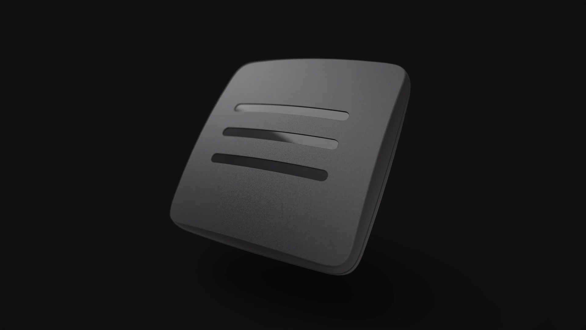
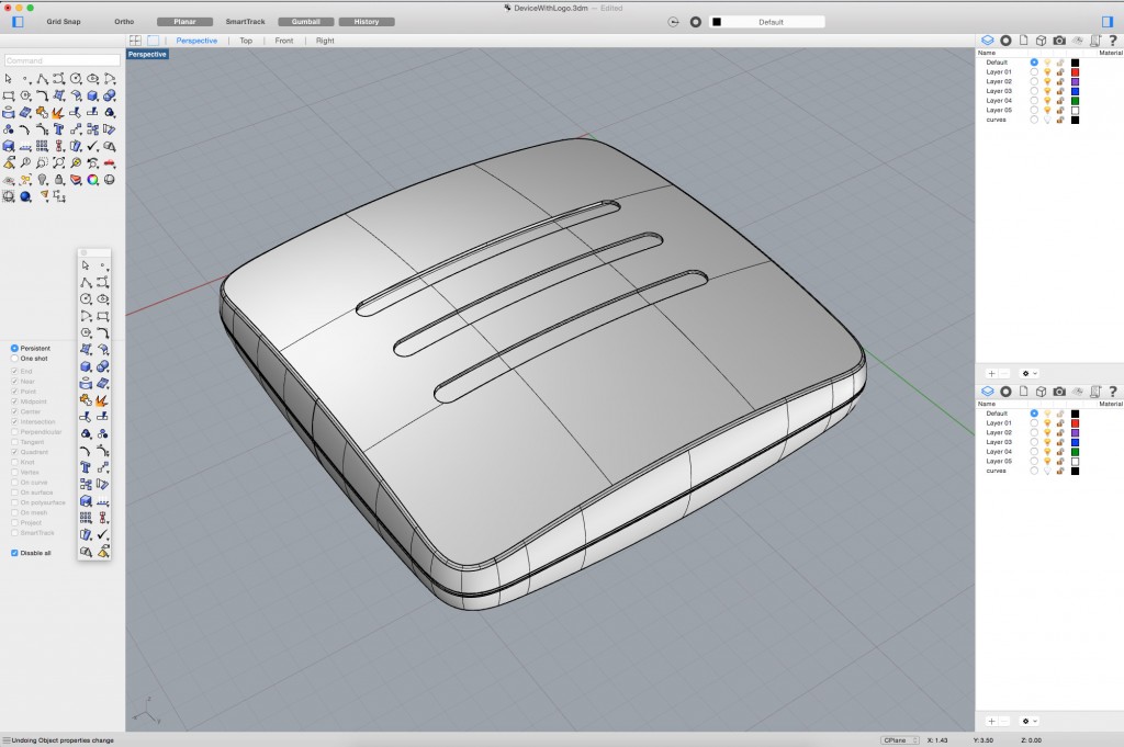
Bring up your CAD model in you CAD software. To have something to show in this tutorial I quickly modeled up this device looking thing. The three slightly recessed lines in the middle makes it out for the soon to be shiny logo!
STEP 2
Select the surfaces that you want to separate from the rest of the part and assign a random color to them (if you are not sure about how to do this in your CAD software, find out, and come back quickly). Surfaces that have the same color will get the same material within KeyShot. By having this model split up into two colors, the grey and the pale yellow, makes us able to assign two different materials to it.

STEP 3
Open up KeyShot and import the model. Yaikes! This doesn’t look very sexy. Move on as fast as possible.

STEP 4
Start by adding the materials you want to your model. In my case I simply drag the standard Plastic Hard Rough Black material to the main body and the standard Plastic Hard Shiny Black material to the logo (the pale yellow area).
And that is actually it. Easy, right? We have now visualized two different surface structures on a single CAD part.

EXTRAS
To really show the effect of the difference in the surface structures I did a few tweaks and created a small gif-animation for you. The tweaks included:
- Adding a bump map to the rough surface to give a bit of extra detail.
- Inducing a tad of roughness to the shiny part as almost nothing is 100% smooth in real life.
- Applying an environment with sharp transitions between light and dark to enhance the effect of the shiny logo.

That’s it! I hope you found it useful. Please ask any questions you might have.
Best regards,
Esben Oxholm